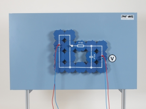
Charging and discharging a capacitor Principle The change in the voltage over time when a capacitor is charged and discharged is to be examined. To maintain consistency with regard to the equipment used throughout the set of experiments described in this handbook, the experimental procedure described below is that for demonstration measurement equipment. Benefits - No additional cable connections between the building blocks needed - clear arragned and quick setup
- Contact saftey due to puzzle blocks system
- Corrosion-free gold plated contacts
- Doubled earning sucess: Electric circuit diagram on top, real components can be seen unterside
Scope of delivery |
PHYWE Demo Physics board with stand
|
02150-00
|
1
| |
Connector, straight, module DB
|
09401-01
|
3
| |
Connector, angled, module DB
|
09401-02
|
5
| |
Connector, T-shaped, module DB
|
09401-03
|
3
| |
Connector interrupted, module DB
|
09401-04
|
2
| |
Switch, change-over, module DB
|
09402-02
|
1
| |
Resistor 47 kOhm,module DB
|
09415-47
|
1
| |
Capacitor(ELKO)0.047 mF,module DB
|
09445-47
|
1
| |
Capacitor(ELKO),0.1 mF,module DB
|
09446-10
|
1
| |
Capacitor(ELKO),0.47 mF,module DB
|
09446-47
|
1
| |
Connecting cable, 32 A, red, various lengths
|
07363-01
|
2
| |
Connecting cable, 32 A, blue, various lengths
|
07363-04
|
2
| |
PHYWE Power supply, universal, analog display DC: 18 V, 5 A / AC: 15 V, 5 A
|
13503-93
|
1
| |
Electr.symbols f.demo-board,12pcs
|
02154-03
|
1
| |
PHYWE Demo Multimeter ADM 3: current, voltage, resistance, temperature
|
13840-00
|
1
| |
G-clamp
|
02014-01
|
2
|
|


